I. Product Introduction
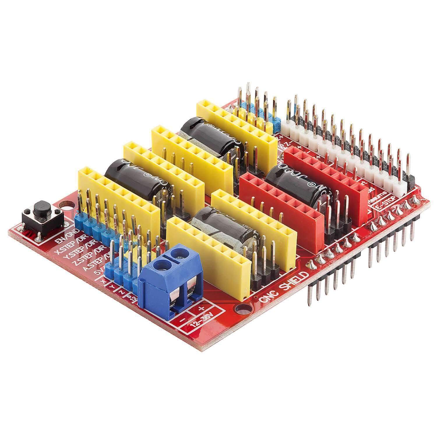
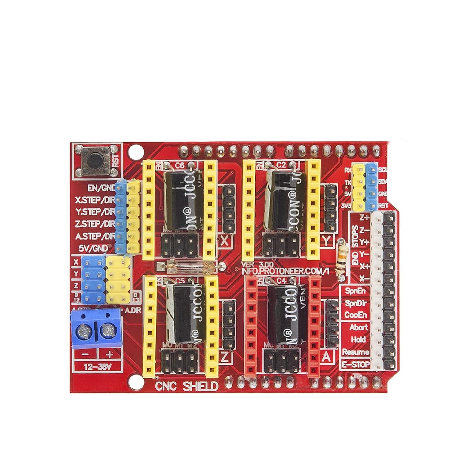
This expansion board can be used as a driver expansion board for CNC machines, 3D printers, etc. It has a total of 4 slots for stepper motor drive modules. (Note that this board does not include the A4988 stepper motor drive module. You can purchase it separately at our store.) It can drive 4 stepper motors, and each stepper motor only requires 2 I/O ports. That means, with 6 I/O ports, you can effectively manage 3 stepper motors. It is very convenient to use and eliminates the cumbersome operation of traditional stepper motors.
II. Introduction to the Correspondence between UNO and Module I/O Ports
The basic control pins required for a stepper motor, the other pins are only used in CNC machines or 3D printers. We won't go into details about them here. The IO connections are as shown in the figure above.
---------------------- Expansion Board
8 ------------------------ EN (Stepper Motor Drive Enable Port, Low Level Active)
7 ----------------------- Z.DIR(Z-axis direction control)
6 ----------------------- Y.DIR (Direction control of the Y-axis)
5 ----------------------- X.DIR (Direction control of the X-axis)
4 ---------------------- Z. STEP (Z-axis step control)
3 ---------------------- Y.STEP (Stepping control for the Y-axis)
2 ---------------------- X. STEP (Stepping control along the X-axis)
// Below is a simple program for controlling a stepper motor,
#define EN 8 // Enable signal for stepper motor, low level is valid
#define X_DIR 5 // X-axis: stepper motor direction control
#define Y_DIR 6 // Direction control for the y-axis stepper motor
#define Z_DIR 7 // Z-axis: Control for stepper motor direction
#define X_STP 2 // X-axis step control
#define Y_STP 3 // Y-axis step control
#define Z_STP 4 // Z-axis step control
/*
// Function: step Function: Controls the direction and number of steps of the stepper motor.
// Parameters: dir - Direction control, dirPin corresponds to the DIR pin of the stepper motor, stepperPin corresponds to the step pin of the stepper motor, steps - The number of steps for the stepper motor
// No return value
*/
void step(boolean dir, byte dirPin, byte stepperPin, int steps)
{
digitalWrite(dirPin, dir);
delay(50);
for (int i = 0; i < steps; i++) {
digitalWrite(stepperPin, HIGH);
delayMicroseconds(800);
digitalWrite(stepperPin, LOW);
delayMicroseconds(800);
}
}
void setup() {
// Set the IO pins used for the stepper motor to output mode
}
pinMode(X_DIR, OUTPUT); pinMode(X_STP, OUTPUT);
pinMode(Y_DIR, OUTPUT); pinMode(Y_STP, OUTPUT);
pinMode(Z_DIR, OUTPUT); pinMode(Z_STP, OUTPUT);
pinMode(EN, OUTPUT);
digitalWrite(EN, LOW);
}
void loop(){
step(false, X_DIR, X_STP, 200); // X-axis motor: Reverse for 1 full circle, 200 steps equal one circle
step(false, Y_DIR, Y_STP, 200); // Y-axis motor: Rotate 1 full circle, 200 steps represent one circle.
step(false, Z_DIR, Z_STP, 200); // Z-axis motor: Rotate 1 full circle, 200 steps represent one circle.
delay(1000);
step(true, X_DIR, X_STP, 200); // X-axis motor rotates forward for 1 full circle, and 200 steps constitute one circle.
step(true, Y_DIR, Y_STP, 200); // Y-axis motor rotates forward for 1 full circle, and 200 steps represent one circle.
step(true, Z_DIR, Z_STP, 200); // Z-axis motor rotates forward for one full circle. 200 steps constitute one complete circle.
delay(1000);
}
Experimental phenomenon: The stepper motor rotates in reverse for one cycle, pauses for 1 second, then rotates forward for one cycle, and this process repeats.
It is worth noting that: When connecting the A4988 module, be sure not to insert it in the wrong direction. The wiring method for the stepper motor is:
2A and 2B form one group (red, green), while 1A and 1B form another group (blue, yellow). To change the direction, simply swap the positions of one of these groups. For example, swap 2A with 2B.