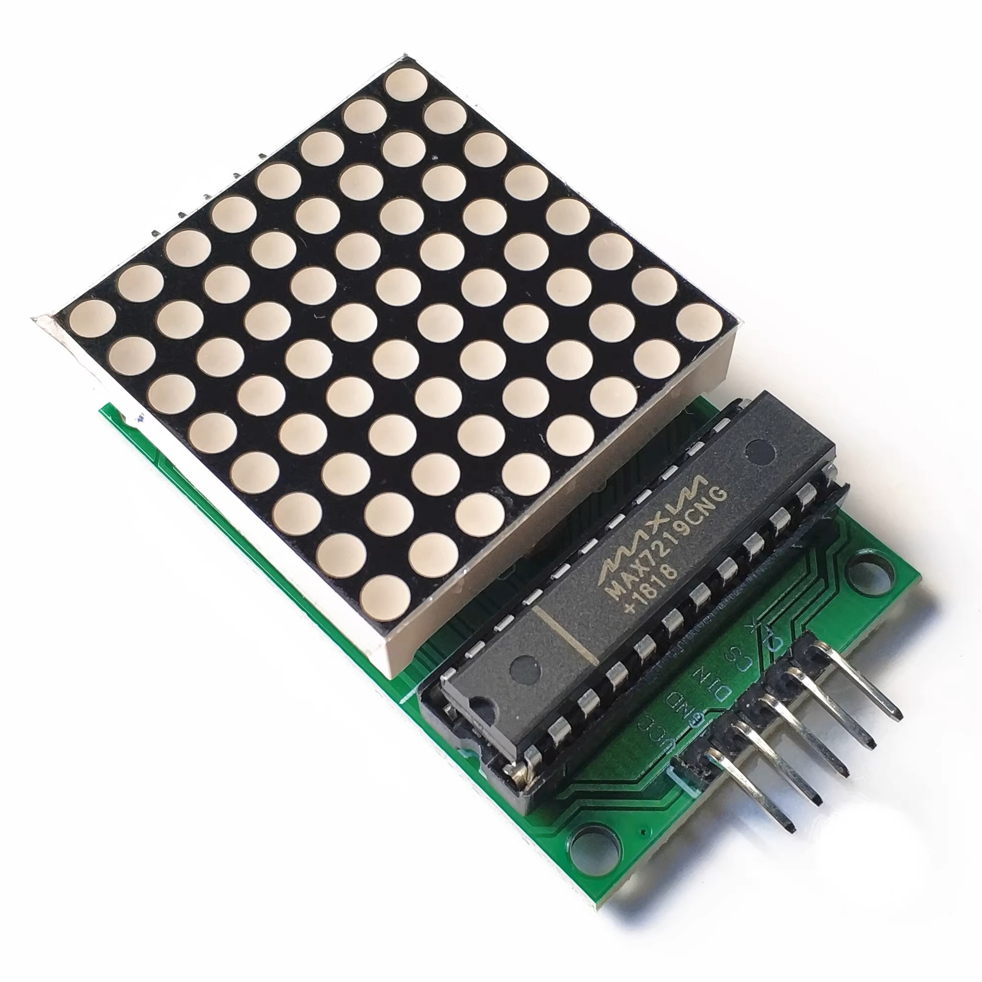
The MAX7219 is an integrated serial input/output common-cathode display driver. It connects the microprocessor to an 8-bit 7-segment digital LED display, or it can be connected to a bar graph display or 64 independent LEDs. It includes an on-chip B-type BCD encoder, multiple scanning circuits, segment and character drivers, and an 8x8 static RAM for storing each data. Only one external register is used to set the segment current of each LED.
A convenient four-wire serial interface can connect all common microprocessors. Each data can be addressed without rewriting all the displays during updates. The MAX7219 also allows users to choose whether to encode or not for each data.
The entire device includes a 150μA low-power sleep mode, analog and digital brightness control, a scan limit register that allows users to display 1-8 bits of data, and a detection mode that enables all LEDs to light up.
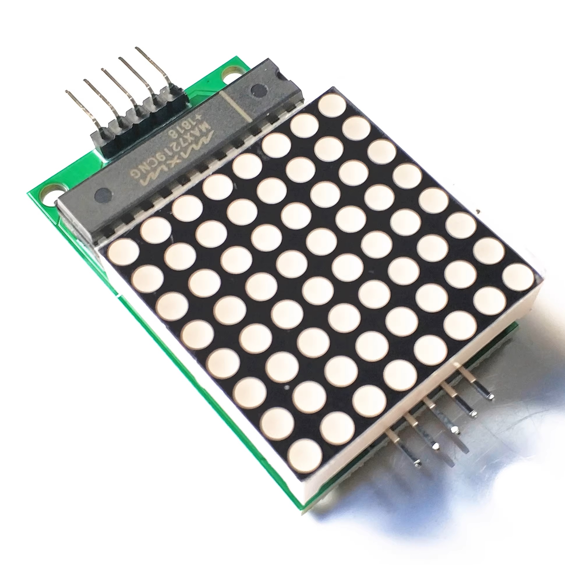
Only 3 I/O ports are needed to drive a 1x1 dot matrix! There is no flickering during dot matrix display! It supports cascading!
Module Parameters:
A single module can drive an 8*8 common-cathode dot matrix.
2. Module operating voltage: 5V
3. Module dimensions: Length 5 cm x Width 3.2 cm x Height 1.5 cm
4. Comes with 4 fixed screw holes, with a diameter of 3mm. Can be fixed using the M3 copper rods sold in our store.
5. The module is equipped with input and output interfaces and supports cascading of multiple modules.
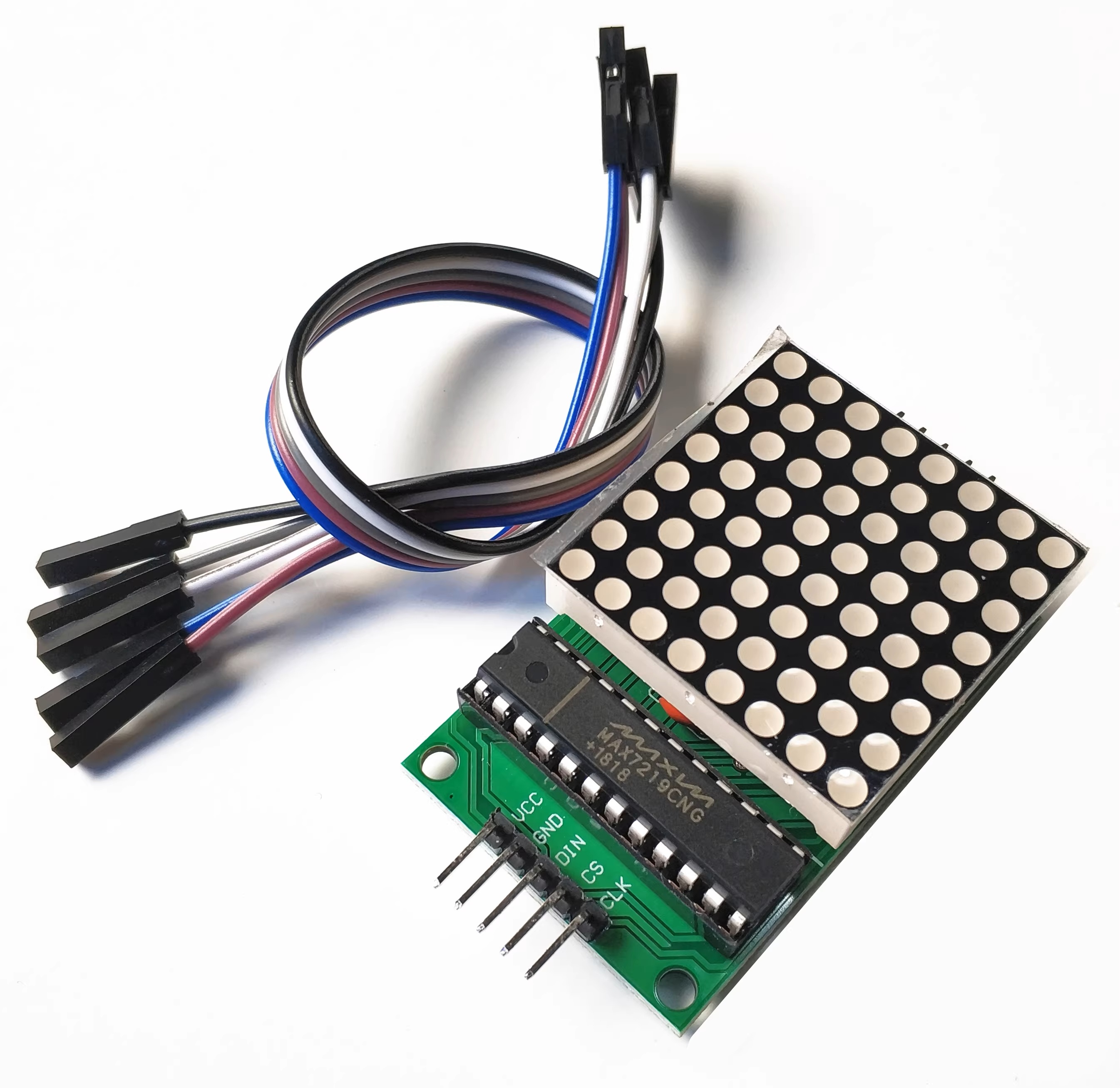
Connection Instructions:
On the left side of the module are the input ports, and on the right side are the output ports.
2. When controlling a single module, simply connect the input port to the CPU.
3. When multiple modules are cascaded, the input end of the first module is connected to the CPU, the output end of the first module is connected to the input end of the second module, the output end of the second module is connected to the input end of the third module, and so on...
Take the 51 microcontroller as an example:
VCC → 5V
GND → GND
DIN → P22
CS → P21
CLK → P20
We focus on three core product categories to meet diverse market demands:
1、Passive Components: We offer a comprehensive range of resistors, capacitors, inductors, and connectors, backed by stable stock and competitive pricing to support your continuous production needs.
2、Integrated Circuits (ICs) & Microcontrollers: Our portfolio features high-performance chips, including the ESP32 series, MCUs, and logic ICs. All components are sourced from authorized distributors to ensure guaranteed quality and authenticity.
3、PCB & PCBA Solutions: We provide complete supply chain support for printed circuit boards, ranging from prototype fabrication to mass production assembly, serving the IoT, consumer electronics, and industrial sectors.
4、Quality & Service Commitment
At Muren Technology, we prioritize authenticity and traceability. Every batch undergoes strict quality inspection with full lot traceability and customs declaration support. Whether you require samples, small-batch trials, or large-volume orders, our professional team ensures accurate delivery and long-term stable cooperation.


